By subscribing you agree to with our Privacy Policy
PORTABLE MILLING MACHINE PART 2: ASSEMBLY
March 27, 2024
TRAMMING THE PORTABLE MILLING MACHINE ASSEMBLY
As promised last week, we are giving you a closer look at the portable milling machine head assembly and how to get the results you’re looking for as you begin machining with your CLIMAX portable milling machines. We’ll review the key steps and issues associated with tramming the milling assembly.
“When it comes to fine adjustability, we have given the CLIMAX portable mills the same adjustments you would see on a precision stationary mill. Tramming the spindle is key to milling a precision “flat” or “square” surface,” says Jim Miller, senior product and Applications Expert for CLIMAX.
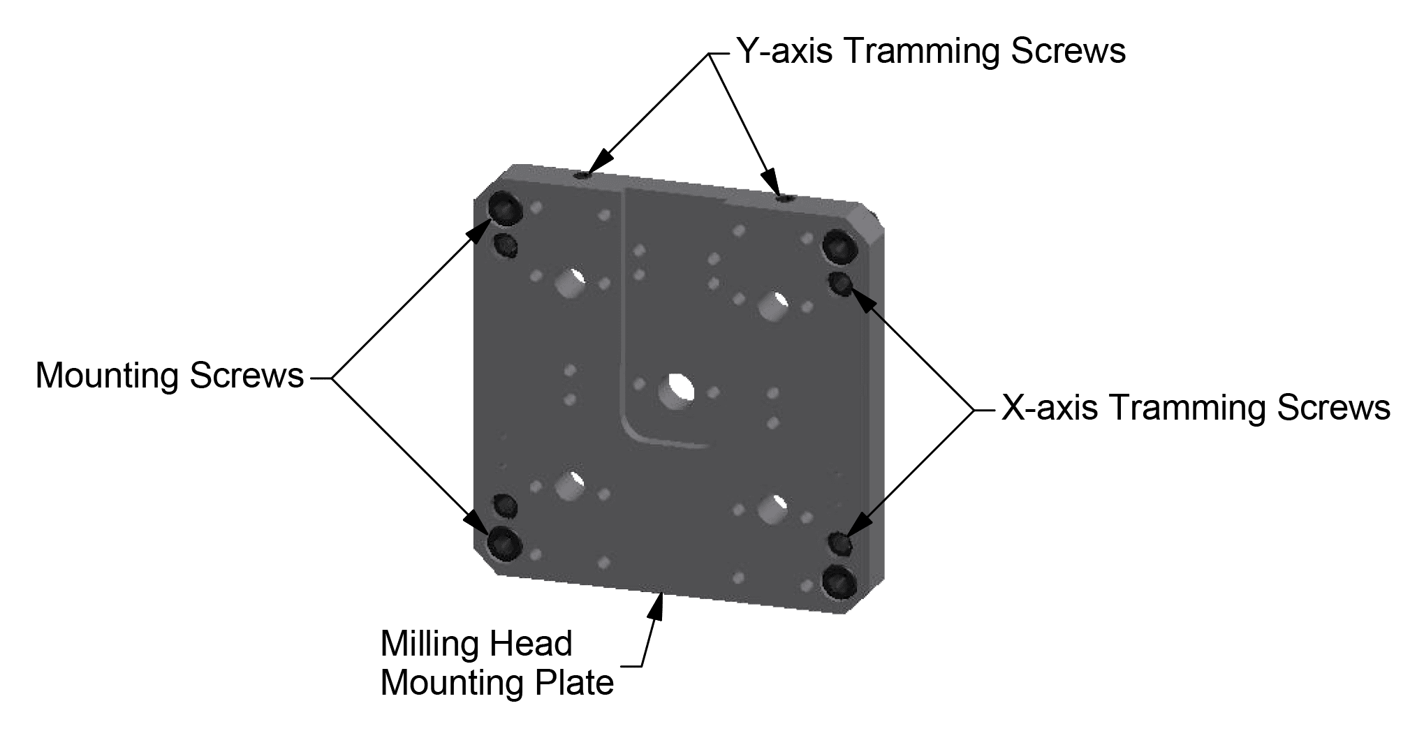
The tramming plate is precision-machined to be parallel to the ram and perpendicular to the bed. In many cases, the standard alignment of the milling assembly will be sufficient. If more precision is needed, the milling head mounting plate is supplied with tramming screws for fine adjustments. Repair technicians can use the screws to adjust the quill housing away from the mounting plate to adjust the x-axis orientation. Also, moving the vertical adjusting screws up and down (which rotates about the center pin) for tramming the y-axis orientation of the milling assembly.
Here’s how:
- Make sure the power is disconnected.
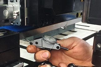
- Attach a dial indicator with a magnetic base to the end of the spindle.
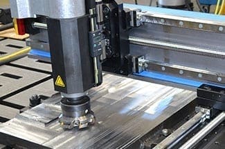
- If the drive motor is installed, remove it from the spindle gearbox to enable easy hand rotation of the spindle (Image 1).
- Position the milling assembly so that you can reach the bottom of the ram or the linear bed rails (image 2).
|
|
|
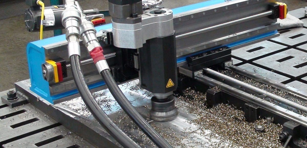
- Now, sweep the datum surface of the bed or ram with the indicator by rotating the spindle by hand.
- Finally, tram the direction along the Y-axis by adjusting the top tramming screws. Then tram the direction along the X-axis by adjusting the tramming screws on the milling head mounting plate. The mounting screws will have to be loosened slightly to make these adjustments. When both directions are adjusted, tighten the mounting screws (below).
- Remove the magnetic base and dial indicator, and reinstall the drive motor.
Do you have a question about portable milling machine setups that we didn’t cover here? Or is there a product you would like to learn more about? Contact us today, and our team will get back to you promptly!